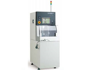
Model: DAD321
The Disco Wafer Dicer is a automatic machine, suitable to dice wafer.
Specification:
- Wafer Size: 6”
- Wafer Material: Silicon and Pyrex glass wafers
- Min bade width: 0.2mm
Design Rules:
- The devices with features like diaphragms are to be minimum 25 microns thickness to be diced, if not they can be released after dicing.
- Maximum wafer size, circular 6” and square 4”, thickness of maximum 1.2mm
- Material of wafers can only be Silicon, Glass and bonded wafers.
- Saw Street/ gap between dies has to be minimum 0,4 mm
- Die size should be a minimum 1.5 x 1.5 mm
- The pitch in ‘X’ and ‘Y’ should be consistent though the whole wafer, including the spacing provided for alignment marks
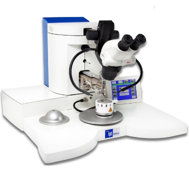
Model: HB16
TPT Wirebonder is semiautomatic machine to establish connectivity between die and substrate.
Specification:
- Wire material: Au (25µ) & Cu, Al (33µ)
- Bonding type: Ball bonding, Wedge bonding & Ball Bump
- Minimum bond pad size: 150×150µ, pad pitch of 200µ
- Distance btw 1st & 2nd Bond: btw 1-5mm length
- Metallization thickness of 100nm of material Au/Al with a bond pad appropriate seed layer
- Wire Dimension: 17-75µ
- Ribbon max: 25×250µ
- Axis Control: Motorized Z & Y,Manual X
- Vertical Access Depth: 16mm
- Ultrasonic System: PLL control 62KHz transducer
- Ultrasonic Power: 0-2 Watt output
- Bond Time: 15 – 2,000 msec
- Bond Force: 15-150 cN
- Heater Stage Controller: Built-in 250 C max
- Electric Requirements: AC 220V,Single Phase,50Hz
Design Rules:
- Bond pad size to be minimum 200 X 200 um with a pitch of minimum 300 um
- Bond pad metallization thickness to be minimum 80nm, with a appropriate seed layer
- Available wire sizes Au (25 um) and Al (33 um) wires
- Thin film materials should be deposited using suitable clean room processes with good mechanical properties such as surface roughness scratch resistant and hardness
- The devices should be desiccated properly and without any formation of an oxide layer.
- Attachments for wire pull gauge to test the pull strength available
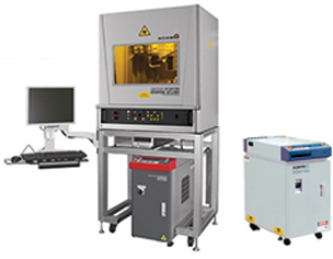
Model: LW70AE
Laser Welding machine has capability of Spot and Seam welding MEMS packages made of metals and alloys such as SS304/304L/316/321, Kovar, Invar etc.
Tool Specifications:
- Type: Delta BDMS four (4) axis
- Enclosure: 40″W x 26″D x 40″H
- XY Table: M6″ x 6″
- Power Supply: 220 VAC, 50 Hz
- Work Holding: 5″ rotary stage with 3-jaw chuck & Collets
- Work Holding Capacity: 50mm diameter parts
Laser secifications:
- Type: Nd-YAG
- Coolant: Water Cooled
- Pulse Duration: 0.25-30ms
- Power Supply: 400 VAC, 3 – phase
- Max Avg Power: 70W
- Max Pulse Energy: 70J
- Wavelength: 1064nm
- Pulse repetition: 1-200Hz
Design Rules:
- Nd-YAG based welding machine
- Spot and continuous welding capability, with a spot size of a minimum 0.3mm and penetration of 0.7mm can be accomplished
- Work holding can accommodate a maximum component diameter of 40mm.
- Laser parameters are tuned to weld metals and alloys such as stainless steel and Kovar only
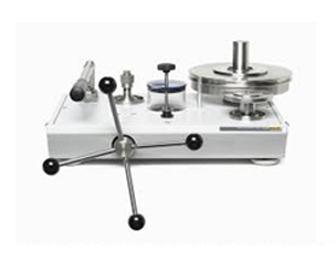
The Hydraulic Pressure Calibrator is dual piston dead weight tester primary standard tested for a pressure range of 0 to 1200 bar.
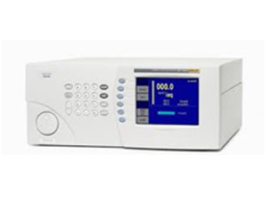
Pneumatic Calibrator is a digital pressure controller for a pressure range of 0 to 20 bar with data acquisition system.
These calibrators are available for pressure transducer testing and calibration.
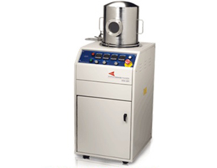
The PDS is a vacuum system used for the vapor deposition of the Parylene-C polymer onto a variety of substrates. The clear polymer coating formed provides an extremely effective chemical and moisture barrier with high dielectric and mechanical strength.
Specification:
- Dimensions Width, (Nominal) Height, Depth: 19.5 in (49.5cm),50.5 in (128.3cm),23.75 in (60.4cm)
- Chamber Size: 12 inch dia. X 12 inch high (8.5”/31.5cm Dia. X 11.19”/28.4cm H, useable size)
- Power: 110/220 VAC, single phase, 50-60 Hz, 20/12 A
- Dimer Capacity: 125 grams
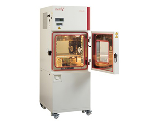
Model: VCL7003
This Hot and Cold Enclosure / Test Chamber is used for evaluating device quality, reliability and identify manufacturing flaws on MEMS devices.
Tool Specifications:
- Test space volume: 34 Lts
- Test Space Dimension: 350W x 300D x 310H mm
- Temperature Range for temperature tests: -700 C to +1800 C
- Temperature Range for climatic tests: +100 C to +950 C
- Humidity range: 10% r.h to 98% r.h
- Dew Point range: +5.50 C to +950 C
- Entry port Dimensions: Entry port, Ø 50 mm, r. h. side
- Data capture: Simpati, Software Package
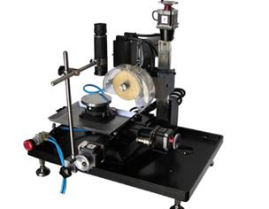
Model: EC-400
The MTI Cut Wafer Dicer is semiautomatic machine, suitable to dice wafer of maximum size 4”. Wafer material can be Sillicon & Glass. The blade width is 0.35mm, device pitch should be around 2.5mm to facilitate angular alignment.
Specifications:
- Accuracy: 2.5µ moving resolution, 0.01mm position accuracy.
- Cutting Blades: 4” dia x 0.35mm thick fully sintered diamond blade
- Control Mode: Manual control/PC control
- Cutting Range: X-axis:4”, Y-axis:4”,Z-axis:4”
- Water Cooling: Water jet
- Power Consumption: 180W
- Voltage: AC220V, Single Phase, 50Hz
- Motor: DC motor 110V,variable speed max 3000rpm
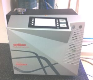
- Make Oerlikon Leybold
- PhoeniXL300TL7
- Portable
- Min detectable helium leak rate Vacuum mode < 5×10-12 mbar x l/s Sniffer mode < 1×10⁻⁷ mbar x l/s
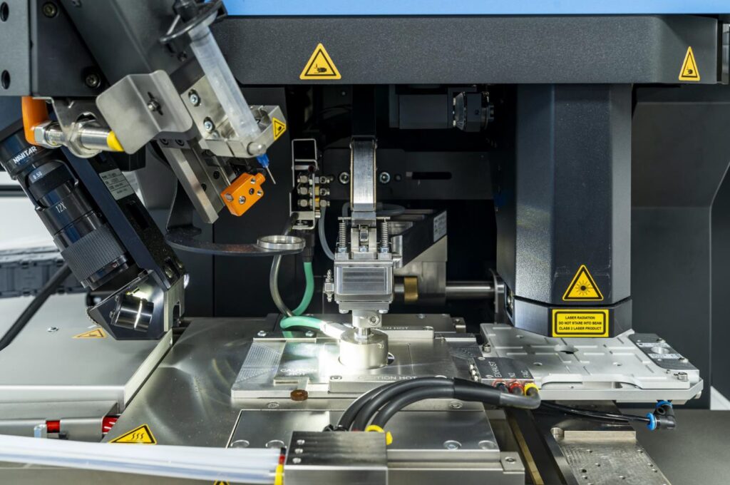
- Wafer Grinder
- Wafer Dicer
- Die Bonder
- Automatic Wire bonder
- Shear Tester
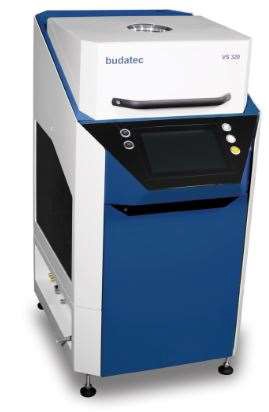
Vacuum Soldering Reflow Systems
Vacuum soldering reflow systems use a combination of pressure control, thermal profiles, and gas control to create bonds that are nearly void-free
and flueless. The VS 320 is a vacuum soldering system with a 320 mm x 320 mm heating plate size that’s suitable for research and development, as well as producing medium and large batches. Here are some more details about the VS 320 and vacuum soldering reflow systems:
VS 320
This system can be extended to a combined system with the SP 60 sintering press, which allows for the production of sintered joints under reduced or inert atmospheres. It also oers a variety of options, including hydrogen, HCOOH, special gases, microwave plasma, and sintering press.
Inline vacuum soldering systems
These systems can run various cleaning and soldering processes simultaneously within a single system. This is because the heating, cooling, and vacuum process steps take place in the same process chamber.
Vacuum reflow ovens
Some vacuum reflow ovens can automatically refill formic acid when the level in the bubbler drops below a certain level. This option is recommended for production purposes where a larger amount of formic acid is required.
Technical Data
- Plate size: 320 x 320 mm2
- Chamber height: 100 mm
- Max. soldering temperature: 450 °C
- Heating- / Coolingramp: 2 K/s
- Max. load: 15 kg
- Process atmosphere: N2, N2H2 (95/5)
- HCOOH, H2 (up to 100%)
- Power supply: 400 V / 32 A
- Cooling Water: 20 slm
Features
- Process-Control via separate thermocouples
- Graphical overview of process components
- Digital manual integrated in the software
- Maintenance reminder
- Proposal for changing necessary components at the end of lifetime
- Power monitoring to detect defective heating rods
- Monitoring of energy consumption (Industry 4.0)
- Optional manipulation inside the chamber
- Optional sintering device SP 60
Standard Operating Procedure (SOP)
SOP of few equipment are given below and this is for reference only. Contact the links if u need further details.
| Revision | Date | Initiator | Reviewer Signature | Approver’s Signature |
| 1 | 12 Dec 2017 | Manjunath | Jayabal | MM Nayak |
1. Purpose
This document describes the steps to be followed by the user, to weld components.
2. Scope
It covers the instructions for basic operations of the system, the safety precautions to be followed while operating the system and the penalty, in case of any deviations from following SOP.
3. Points to be noted before starting the tool
- Check if all the facilities like Coolant water, Argon gas is turned on.
- Never run the laser with the laser protection door opened, by overriding the interlock.
- CNC part program of the component to be ready before starting the machine.
- Clean the mating parts of the components using Acetone and IPA
4. Operating Instructions
- Sample Loading and welding
- Turn-on the laser source, work holding machine and log-in in into the system
- Load the sample on to the chuck
- Dry run the part program by disabling the laser to confirm the part program is defect free.
- Activate the laser source and weld the component.
- Any malfunction the emergency switches should be pressed immediately.
- Sample Unloading
- Once the welding process is finished the sample can be removed from the chuck
5. Precautions
- Never run the laser with the laser protection door opened, by overriding the interlock.
- Dry run the part program by disabling the laser to confirm the part program is defect free.
- Activate the laser source and weld the component.
- Any malfunction the emergency switches should be pressed immediately.
6. Contact Point
If you feel any difficulty while operating or any issue with the tool. Please contact the tool owners
Manjunath: 9731387979
Jaybal: 9886058035
Laser Tool pictures:
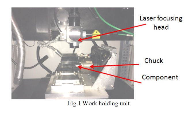
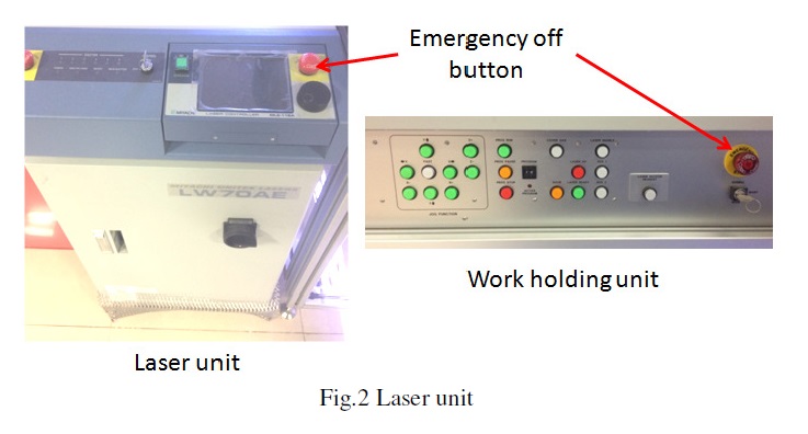
If any other than above stated, Please contact the tool owner.
NOTE:
Any deviations from this SOP will be considered as a breach of User Agreement conditions and will result in cancellation of access to the tool.
| Revision | Date | Initiator | Reviewer | Approver’s Signature |
| 1 | 21 Dec 2017 | Manjunath | Pavitra /Manjunath | MM Nayak |
1. Purpose
This document describes the steps to be followed by the user, to calibrate pressure sensor device.
2. Scope
It covers the instructions for basic operations of the system, the safety precautions to be followed while operating the system and the consequences, in case of any deviations from following SOP.
3. Points to be noted before starting the tool
- Make sure beforehand the device is leak proof and can withstand high pressures at-least 1.5 times the actual operating pressure.
- Mount the device with appropriate fittings and ‘O’ rings, only hand tight the device.
- Release the relief valve and prime the tool by pressurizing and depressurizing and verify that there are no air bubbles.
4. Operating Instructions
- Sample Loading and welding
- Mount the sensor always upright and do a leak test at low pressures and close the relief valve.
- Gradually increase/decrease the pressure/depressurizing by adding /removing the weights in suitable increments and calibrate the sensor.
- Sample Unloading
- Make sure to unload the component only after depressurizing and opening of the relief valve.
5. Precautions
In-case of any emergency depressurize and open the relief valve
6. Contact Point
If you feel any difficulty while operating or any issue with the tool. Please contact the tool owners
Pavitra: 9449947188
Manjunath: 9731387979
Equipment Picture
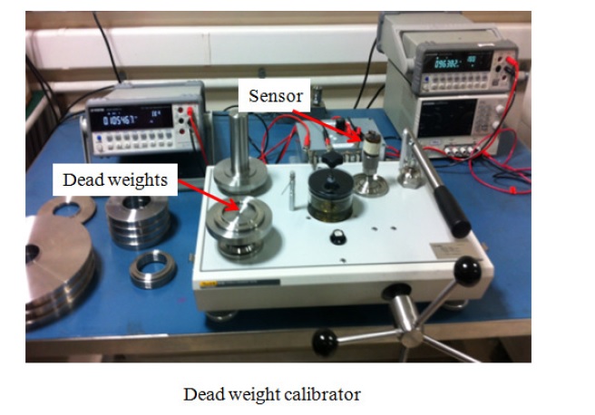
If any other than above stated, Please contact the tool owner.
NOTE:
Any deviations from this SOP will be considered as a breach of User Agreement conditions and will result in cancellation of access to the tool.
| Revision | Date | Initiator | Reviewer | Approver’s Signature |
| 1 | 12 Dec 2017 | Manjunath | Shankaran /Manjunath | MM Nayak |
1.Purpose
This document describes the steps to be followed by the user, to calibrate pressure sensor.
2. Scope
It covers the instructions for basic operations of the system, the safety precautions to be followed while operating the system and the consequences, in case of any deviations from following SOP.
3. Points to be noted before starting the tool
- Cordon off the area around the tool.
- Mount the device with appropriate fittings and point the device away from operator.
- Make sure beforehand the device is leak proof and can withstand high pressures at-least 1.5 times the actual operating pressure.
4. Operating Instructions
- Sample Loading and welding
- Mount the sensor which has to be calibrated and do a leak test at lower pressures (10-20) bar and slowly increase the pressure by closing the input check valve and check for any pressure drop.
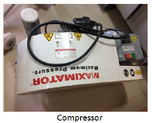
- Increase the pressure gradually up to 300 bar and close the release valve and turn off the compressor.
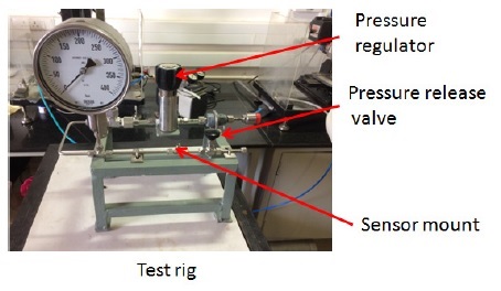
- Ascending pressure test – Test the sensor by gradually increasing adjusting the pressure regulator to the required steps of pressure
- Descending pressure test – by gradually releasing the pressure using the pressure release valve in the required steps.
- Sample Unloading
- Once the calibration is completed depressurize by opening the relief valve completely and unload the sample.
5. Precautions
- In-case of any emergency turnoff the Maximator Compressor and release the pressure immediately by turning the pressure release valve.
6. Contact Point
If you feel any difficulty while operating or any issue with the tool. Please contact the tool owners
Sankaran: 9632839996
Manjunath: 9731387979
Equipment Picture
